3.2.1. Create OcTree Mesh Input File
OcTree meshes used in the E3DMT code are created using the program create_octree_mesh_e3dmt.exe. Parameters necessary for defining the OcTree mesh are set in the input file. The lines within the input file are as follows:
Line # |
Parameter |
Descriptions |
|---|---|---|
1 |
min. cell widths in x, y and z for base mesh |
|
2 |
sets the extend of mesh in x, y and z direction |
|
3 |
sets cell sizes within core mesh region |
|
4 |
sets thickness of cells of finest discretization near receivers |
|
5 |
the file containing observation locations |
|
6 |
sets topography |
|
7 |
description needed. leave as NOT_SHIFT_DATA |
|
8 |
sets level of discretization for surface topography |
|
9 |
sets the starting point for the mesh generation |
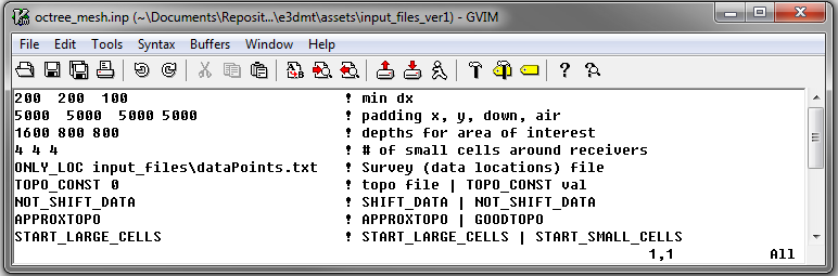
Fig. 3.1 Example input file for creating octree mesh (Download )
3.2.1.1. Line Descriptions
dx dy dz: Minimum cell widths in x, y and z for the base mesh.
x_pad y_pad down_pad up_pad: Distance from the origin in the x, y, downward and upward directions, respectively, that the mesh extends.
Important
In the case where you are modeling ZTEM data and the base station is very far from the general survey region, you MUST ensure the padding extends far enough to contain the base station. Otherwise, the mesh generation will fail.
dist_1 dist_2 dist_3: Sets the distance from surface topography and receivers in which the cells widths are increased by a factor of 2 in x, y and z. Up to a depth of dist_1 from surface topography and within a horizontal distance of dist_1 from any receiver, the smallest cell size is used (set by dx, dy, dz). For the following dist_2 metres, the cell widths are doubled. For the following dist_3 metres, the cell widths are doubled again. Outside a depth and horizontal distance of h1+h2+h3, the cells widths increase by a factor of 2 for every additional layer (see the figure below).
n1 n2 n3: This sets the thicknesses of layers of finest discretization near the receivers. n1 = 4 means that around each receiver, there is a layer 4 cells thick that uses the finest discretization. This is followed by a layer which is n2 cells thick, where the cell dimensions are increased by a factor of 2. Likewise for the 3rd layer.
locFile: Contains the locations of the receivers. The user may either enter the file path to an observed data file, or the flag “ONLY_LOC” followed by the path to a data points file.
topoFile: If a topography file is available, the file path to the topography file is entered; see topography file for format. In the case of flat topography, the user instead enter “TOPO_CONST”, followed by a space, then the elevation of the surface topography; for example “TOPO_CONST 125.5”.
shift_data: Here, there are 3 options:
If the flag “NOT_SHIFT_DATA” is used, then it is possible for stations to lie below the topography specified on line 6.
If “SHIFT_TO_SURFACE filename” is used, then a locations file is created in which all stations are projected to be at the discretized surface topography. This is used primarily for MT surveys
If “SHIFT_FLIGHT_HEIGHT filename” is used, then a locations file is created in which the data locations are shifted to preserve true flight height over the discretized surface topography. This is used for ZTEM surveys.
interp_topo: Set as either “APPROXTOPO” or “GOODTOPO”. If “APPROXTOPO” is chosen, there will only be fine cells close to the survey, whereas “GOODTOPO” will place fine cells everywhere on the surface.
start_point: Set as either “START_LARGE_CELLS” or “START_SMALL_CELLS”. This line sets the starting point for the mesh generation. Starting the mesh population from large cells greatly reduces initial memory required and is therefore suggested. Large cells are divided in this algorithm to produce the OcTree mesh.
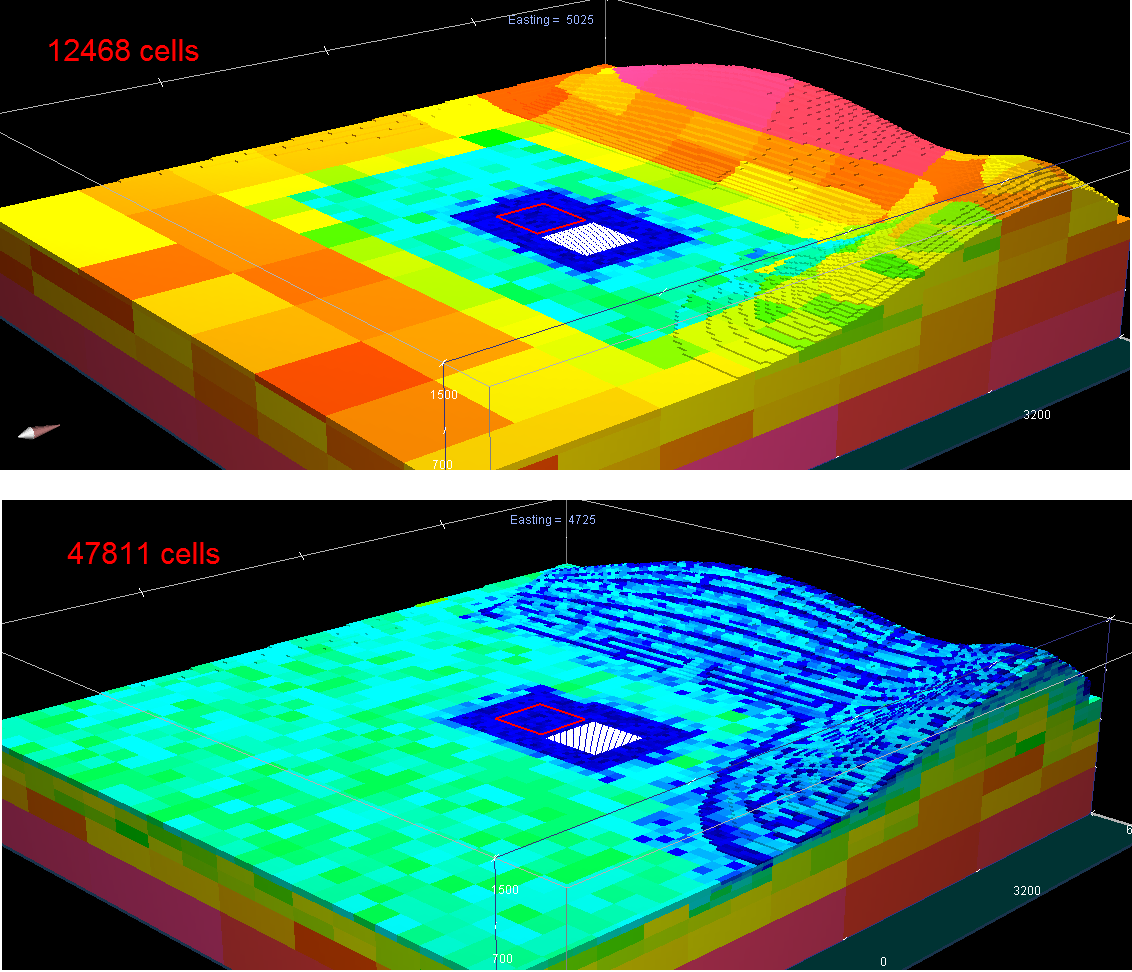
3.2.1.2. Approximate versus Good Topography
Below, we see the difference between entering “APPROXTOPO” (top) and “GOODTOPO” (bottom) into interp_top. For “APPROXTOPO”, the mesh ultimately contains a smaller total number of cells, as discretization near the surface is coarser. For “GOODTOPO”, the mesh contains a larger total number of cells because the surface topography is discretized to the finest cell size.