3.2.2. Create Model Input File
3.2.2.1. Input File and Line Descriptions for blk3cell
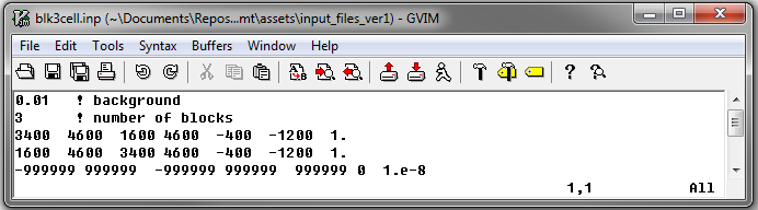
The input file defines the properties of the model (conductivity/susceptibility/active) created using blk3cell.exe. The user specifies the locations, dimensions and values for a set of blocks. All undefined cells within the mesh are set to the background value. The format for this file is as follows:
Line # |
Parameter |
Description |
|---|---|---|
1 |
\(\sigma_b\) |
background conductivity/susceptibility |
2 |
\(N\) |
number of blocks |
3 |
\(x_1^{(1)} \;\; x_2^{(1)} \;\; y_1^{(1)} \;\; y_2^{(1)} \;\; z_{top}^{(1)} \;\; z_{bottom}^{(1)} \;\; m^{(1)}\) |
Block 1 |
4 |
\(x_1^{(2)} \;\; x_2^{(2)} \;\; y_1^{(2)} \;\; y_2^{(2)} \;\; z_{top}^{(2)} \;\; z_{bottom}^{(2)} \;\; m^{(2)}\) |
Block 2 |
\(\vdots\) |
\(\vdots\) |
\(\vdots\) |
\(x_1^{(N)} \;\; x_2^{(N)} \;\; y_1^{(N)} \;\; y_2^{(N)} \;\; z_{top}^{(N)} \;\; z_{bottom}^{(N)} \;\; m^{(N)}\) |
Block 3 |
where superscript \((i)\) for \(i=1,2,...,N\) refers to a particular block. \(x_1,x_2,y_1,y_2,z_{top}\) and \(z_{bottom}\) define the dimensions of each block and \(m\) defines conductivity/susceptibility value. An example is shown below.
3.2.2.2. Input File and Line Descriptions for Model2Octree
The file 3DModel2Octree.inp contains the paths to the tensor mesh (3D_mesh.txt), tensor model (3Dmodel.con) and octree mesh (octree_mesh.txt) as well as other necessary parameters. The format of the input file is as follows:
Line # |
Parameter |
Description |
|---|---|---|
1 |
\(Model \; Type\) |
Either LIN_MODEL or LOG_MODEL |
2 |
\(Octree \; mesh\) |
File path to Octree mesh |
3 |
\(Tensor \; mesh\) |
File path to tensor mesh |
4 |
\(Tensor \; model\) |
3D model on tensor mesh |
5 |
\(Output \; mesh \; name\) |
Name for re-meshed Octree mesh or enter USE_INPUT_MESH |
6 |
\(Output \; model \; name\) |
File name for conductivity model on Octree mesh |
7 |
\(Start \; point\) |
Either START_LARGE_CELLS or START_SMALL_CELLS |
Note
- Consider the following with regards to line 5:
The edges of structures defined within the underlying tensor mesh may bisect larger cells within the Octree mesh. If an output name is provided, the program will output a new Octree mesh with refined cells such that the edges of structures do not bisect cells. Thus the input and output Octree mesh may have a different number of cells.
If USE_INPUT_MESH is entered, the model on the underlying tensor mesh is interpolated onto the pre-existing Octree mesh.
An example input file and the resulting conductivity model on the octree mesh are shown below
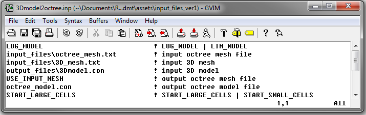
Fig. 3.3 Example input file for 3DModel2Octree.exe (Download )