3.2.1. Create OcTree Mesh Input File
OcTree meshes used in the E3DMT code are created using the program create_octree_mesh_e3dmt_v2.exe. Parameters necessary for defining the OcTree mesh are set in the input file. The lines of input file are as follows:
Line # |
Parameter |
Description |
|---|---|---|
1 |
minimum cell widths in x, y and z for the mesh |
|
2 |
min_cell_fact \(\;\) min_cell_size \(\;\) max_topo_cell |
controls discretization based on padding, topography and receivers |
3 |
sets extent of mesh in x, y and z |
|
4 |
sets discretization in core region |
|
5 |
sets the thicknesses of layers of finest discretization near the receivers |
|
6a |
path to observations file |
|
6b |
path to receivers file |
|
6c |
path to frequencies file |
|
7 |
sets topography |
|
8 |
description needed. leave as NOT_SHIFT_DATA |
|
9 |
sets lateral extent of core region |
|
10 |
name of output mesh |
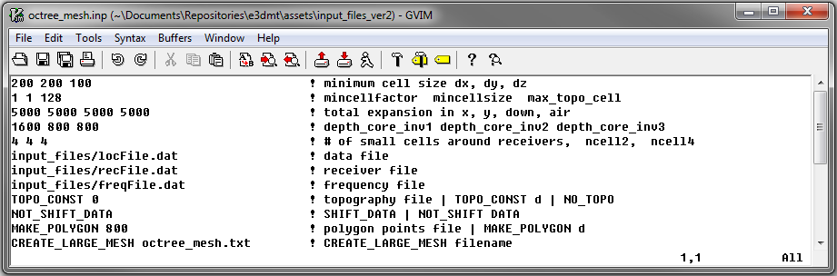
Fig. 3.1 Example input file for creating octree mesh (Download )
3.2.1.1. Line Descriptions
dx dy dz: Minimum cell widths in x, y and z for the mesh.
min_cell_fact: Used to scale the cell values of dist_1 dist_2 dist_3 … dist_n inside the core mesh region. If min_cell_fact = 1, discretization below the Earth in the core mesh region will begin with the smallest cell size. If min_cell_fact = 2, the discretization below the Earth will begin with 2 times the smallest cell size; DEFAULT = 1 . Must be a power of 2.
min_cell_size: For ground-based surveys, this value is redundant; leave as 1. For airborne ZTEM, we may want to specify the cell size between the surface topography and the fine cells around the receivers (n1 n2 n3). Here, min_cell_size is a factor defining the size of these cells relative to the underlying mesh cell size (dx dy dz). max_topo_cell is an integer value equal or greater than 1 and must be a power of 2. DEFAULT = 1 .
max_topo_cell: Far from the core region (padding cells), the user may want to prevent overly large cells from defining the topography. Here, max_topo_cell is a factor defining the maximum cell size relative to the underlying mesh cell size (dx dy dz) that can be used along the surface topography. max_topo_cell is an integer value equal or greater than 1 and must be a power of 2.
x_pad y_pad down_pad up_pad: Distance from the data boundary in the x, y, downward and upward directions, respectively, that the mesh extends. True padding in the octree mesh may be larger since cell sizes must increase by factors of 2.
Important
In the case where you are modeling ZTEM data and the base station is very far from the general survey region, you MUST ensure the padding extends far enough to contain the base station. Otherwise, the mesh generation will fail.
dist_1 dist_2 dist_3 … dist_n: Sets the discretization of the core mesh region below the Earth. Up to a depth of dist_1 from surface topography, the cell size is min_cell_size times the smallest cell size; (min_cell_size) X (dx, dy, dz) . For the following dist_2 metres in depth, the cell widths are doubled. For the following dist_3 metres in depth, the cell widths are doubled again. The user can enter an unlimited number of core mesh layers. Outside a depth and horizontal distance of dist_1+dist_2+dist_3+…+dist_n, the cells widths increase by a factor of 2 for every additional layer (see the figure below).
n1 n2 n3: This sets the thicknesses of layers of finest discretization near the receivers. n1 = 4 means that around each receiver, there is a layer 4 cells thick that uses the finest discretization. This is followed by a layer which is n2 cells thick, where the cell dimensions are increased by a factor of 2. Likewise for the 3rd layer.
Note
You must ensure that the parameter dist_1 is larger than n1 X dz. You will get an error otherwise.
dataFile: E3DMT version 2 can accept observation files written in two different formats (E3DMT version 1 or version 2).
If version 1 file formats are being used, enter the flag V1FORMAT followed by the path to a version 1 formatted data file
If version 2 file formats are being used, simply enter the path to a version 2 formatted data file
receiverFile: file path to the receiver file
If version 1 file formats are being used, this line does not exist in the input file
If version 2 file formats are being used, provide the path to the receiver file
frequencyFile: The file path to the frequencies file
If version 1 file formats are being used, this line does not exist in the input file
If version 2 file formats are being used, provide the path to the frequencies file.
topoFile: There are three options for defining surface topography
Enter the file path to a topography file
For flat topography, enter “TOPO_CONST” followed by a space then the elevation of the surface topography; for example “TOPO_CONST 125.5”
The user may also use the flag “NO_TOPO” to have all cells lie below the surface. For practical applications, this is not recommended
shift_data: Here, there are 3 options:
If the flag “NOT_SHIFT_DATA” is used, then we do not change the locations of the receivers.
If “SHIFT_TO_SURFACE filename” is used, then a receivers file is created in which all receivers are projected to be at the discretized surface topography. This is used primarily for MT surveys
If “SHIFT_FLIGHT_HEIGHT filename” is used, then a receivers file is created in which the data locations are shifted to preserve true flight height over the discretized surface topography. This is used for ZTEM surveys.
If “SHIFT_GENERAL filename” is used, then E-field receivers as well as H-field receivers within a height of 0.1 x the smallest cell size are projected to the discrete surface. For non-surface H-field receivers, flight height is preserved. ADDED 2022-09-27.
MAKE_POLYGON D: The horizontal area covered by the core region is determined by the locations of the receivers and the value of D in metres. Essentially, the code creates a convex hull from all the points defining the receivers. It then extends the convex hull by a distance D. On this line, the user enters MAKE_POLYGON followed by the value D.
CREATE_LARGE_MESH out_name: Here the user enters the flag CREATE_LARGE_MESH followed by the output name for the octree mesh.